
Automotive:
IR-LED Driver for DMS/OMS
Currently, the introduction of Driver Monitoring System (DMS) is progressing in Automotive market, partly due to legal regulations in Europe area.The number of LEDs in series, current and installaion position of DMS vary greatly depending on the size of the vehicle, installaion position, monitoring target , ECU type, etc.
O2Micro provides lineup of appropriate IR-LED Driver for a wide variety of DMS/OMS applications.
Target Applications
Driver Monitoring System(DMS)
Occupant Monitoring System(OMS)
Function of LED driver
Compact PKG with built in main MOSFET
ILED : 1A~5A
Number of LED in series : 1-4 LEDs
Support Power Over Coax (POC)
Limiting function for input current from battery
Limiting function for input power from battery
LED individual failure detection
Noise reduction with LED current soft start
Support Eye safty
Support VCSEL as light source
AEC Q100 suppoted
ASIL/Functional Safety Suppotive
Suport area of TURNER series
※Vin = Battery
Main PCB configuration of DMS
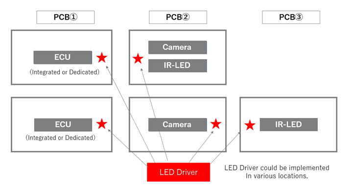
As descrived above, in the DMS, the location of LED Driver IC varies depending on the type of ECU, Camera board and IR-LED board configuration, etc. Therefore, the fuction required by appplictaion vary in addtion to the number of IR-LEDs in series and LED current.
TURNER series provides optimal solutaions for a wide variety of application requirements.
Basic Specifications
| TURNER-1 | TURNER-2 | TURNER-3 | |
|---|---|---|---|
| Input voltage range |
4.5V ~ 36V (abs max. 40V) |
4.5V ~ 36V (abs max. 40V) |
5.5V ~ 40V (abs max. 44V) |
| Operating temperature range | -40°C ~ +125°C | -40°C ~ +125°C | -40°C ~ +125°C |
| Topology | Buck | Boost + Buck |
Buck Inverting Buck Boost |
| LED current | 1A ~ 5A | 1A ~ 5A |
1A ~ 5A (Buck)
1A ~ 2A (IBB) |
| Package | Wettable QFN (4x4mm) | Wettable QFN (5x5mm) | Wettable QFN (4x4mm) |
Features for DMS applications
| TURNER-1 | TURNER-2 | TURNER-3 | |
|---|---|---|---|
| Current/Power limitation | - | O | - |
| Soft-ON / Soft-OFF | O | O | O |
| Single-LED Short detection | O | O* | O |
| Eye-Safety (Pulse width limit) | - | O | O |
| Drive 2 LED strings alternatively | O | O | - |
72CH LOCAL DIMMING LED DRIVER FOR AUTOMOTIVE DISPLAY
EV adoption is speeding up, leading to increased demand for power-efficient local dimming.A tendency to demand image quality equivalent to high-resolution instrument panels for all in-vehicle panels.
Target Applications
Automotive Display: Infotainment Display, Center Information Display (CID), Meter, Cluster, Head-Up Display (HUD), etc
Function of LED driver (OZ590)
- Direct Drive, 72 channels
- Constant sink current LED driver
- Normal mode: ~20mA (72CH ON)
- Boost mode: ~80mA (<10CH ON)
- 15,000:1 dimming ratio
- E-LQFP 100pin package
- DC /DC Feedback control
- High speed SPI communication (SPI daisy chain)
- 3-bit max current control -- ILED(max)=10/20/30/40/50/60/70/80mA
- 7-bit global analog dimming control
- 14-bit individual channel PWM dimming control
- 7-bit individual channel brightness correction (24%~100%)
- Protection
- LED short, LED open
- DRNx short-to-GND
- Over temperature Alert@150°C, Shutdown@165°C
- Easy PCB routing by Bypass function for several signals
- EMI Mitigation
- Slew rate control of LED current
- Selectable SDO output driving capability
- AEC-Q100 support
- ASIL-B supportive
POINTs of selecting local dimming LED driver IC
- How many LED strings driven per IC
- Direct Drive (OZ590): Number of LED strings driven per IC = Number of channels
- SCAN matrix method: Number of LED strings driven per IC = Number of channels * number of scans
- LED current can be boosted up?
- What is the maximum LED current each LED driver IC can support?
- In scan matrix method, need to care rating current of LED.
- Easily routable by 2-layer PCB?
- Direct Drive (OZ590): need to route all cathode lines.
- SCAN matrix method: need to route both all anode and cathode lines.
- Power consumption
- Estimate power consumption by considering;
-
Headroom voltage, with or without DC/DC feedback, LED driving method.
(loss at SCAN switch, narrower PCB routings in SCAN matrix method)
COMPARISON between Direct Drive and SCAN type
| # | Item | Direct Drive (OZ590) | SCAN |
|---|---|---|---|
| 1 |
BETTER LED current = target current |
NORMAL LED current = target current * number of SCAN |
NORMAL LED current = target current * number of SCAN |
| 2 | LED current boost function | ||
| 3 | EMI |
BETTER Low LED current peak |
NORMAL High LED current peak Switch noise of SCAN switch |
| 4 | Thermal |
BETTER Heat generation of IC |
BAD Heat generation of IC, PCB trace, SCAN switch |
| 5 | Mechanical parts and PCB cost |
BETTER Support 2-layer PCB |
NORMAL May be 4-layer PCB or separate PCB |
| 6 | Dimming ratio | BETTER | NORMAL |
| 7 | Control software development |
BETTER Simple |
NORMAL Complicated |